Repairing a
Tail-Twister Rotator
My Tail-Twister rotator was purchased new around 1976 and
has been in constant use since that time. It was originally used with a large Mosley TA-36 with the added, and heavy,
TA-40KR traps to add 40 meters to the driven element. I also usually always have had a
pair of Cushcraft 2 meter twists A144-11T above that, topped with a variety of 2 meter and
VHF/UHF ground planes, so there was always a good amount of windload on the rotator.
I moved it to my present QTH in 1992 but it remained on the same 69 foot Rohn 45 tower
with the same Cushcraft 2 meter beams and various ground planes above it so it has had a
good and hefty windload on it for many years. All during that time it has served me
well.
In 2002, I brought it down and rebuilt it, a job which consisted mostly of a thorough
cleaning, new bearings and races, new direction indicating pot and a complete
relubrication. I've usually kept a spare stainless steel ring gear on hand but I don't
recall replacing that gear at that time. The
rotor swap story is available elsewhere on this website.
It came time to do more work on my rotor again when it developed the strange anomaly of
stopping when pointed around the 90 degree area. With this installation (the center of the
meter scale was on North) it caused some problems. Around Oct of 2005 I had replaced the
Mosley beam with a new 3-element SteppIR, still with
the Cushcraft 2 meter beams and ground plane above it. When my rotor began to have its
stoppage problems when aimed toward the East, the SteppIR became a real life-saver since I
could aim West and use the SteppIR's 180 degree reverse feature to shoot back to the East.
My only problem would come when my excitement and the technology became too intense.
I also have the Rotor-EZ built into
the rotator indicator box and that is attached to my computer while running Logger32
logging and control program. Features in this program allow me to simply click on a
small dot on the map where a new DX station has appeared and my rotator automagically
turns to that location. Logger32 makes it easy to also click on a spot for long path, and
with the 180 degree selection on the SteppIR, that works fine............. except in the
heat of battle........ or a sudden pileup. Without thinking, it's possible to attempt to
send the beam to aim at the new spot, not thinking about the "dead zone."
Several times I let the technology send my array to the East...... Oh No!! Too late.
Once it got the "dead zone," there were only two ways to get out. One was
to either climb the tower and manually turn the antenna away from East while someone below
operated the rotor box (pictures of me at other places on this website help to explain why
my climbing was not an viable option). The other way was to be in the shack when the wind
was blowing hard and when it seemed to be blowing the right direction, I could release the
brake and if the wind was blowing just right, it would move back into the rotator's
"active zone" and I was OK. Unfortunately, although the wind blows often in
Oklahoma (remember the song -- "When the wind goes sweeping down the
plains........"), I was never able to completely anticipate when I needed to perform
this delicate operation. Sometimes, if I was lucky, I could get it back within a day but
there were times when it sat watching the Eastern sky for more than two weeks.
Finally I knew it was time to swap it out, bring it down, and rebuild it. The task went to
Harry - KC5TRB, my expert tower man. He got the
Tail-Twister down without event and move the replacement back in its spot. The temporary
replacement rotator is the Ham II discussed also on these webpages. Right now, after
several months, it has developed some problems and the brake will no longer engage. I
suspect that the spring or springs which draw the brake wedge to its "brake on"
position, has failed. I have a TV camera with microphone mounted just above the rotator
and I can usually hear the brake wedge popping in and out. Now, there is a sound but it is
not a powerful and definite click like it was originally. Only the motor and its gear
train are holding the beam from rotating in the wind........... and they have long ceased
to perform this function. My antenna array is currently freely windmilling like a country
weathervane without a rooster.
I suddenly now have an added incentive to rebuild my trusty Tail-Twister and that is what
this article will describe.
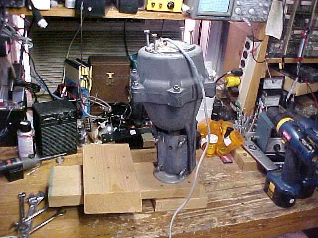 Tail-Twister prior to
opening |
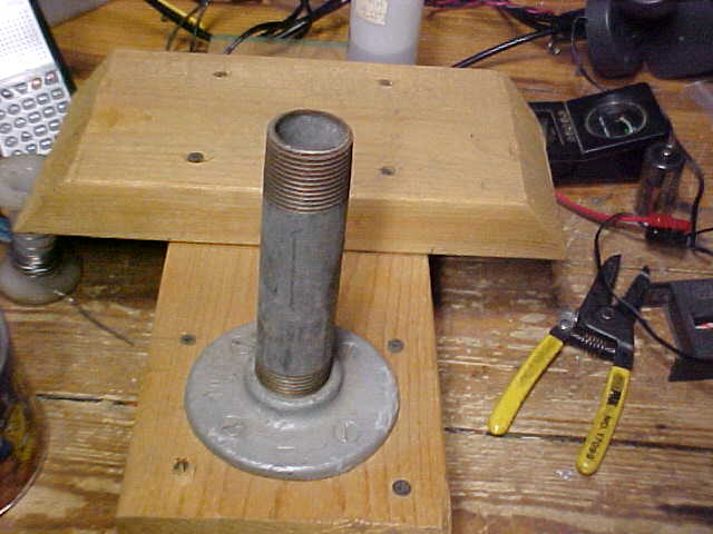
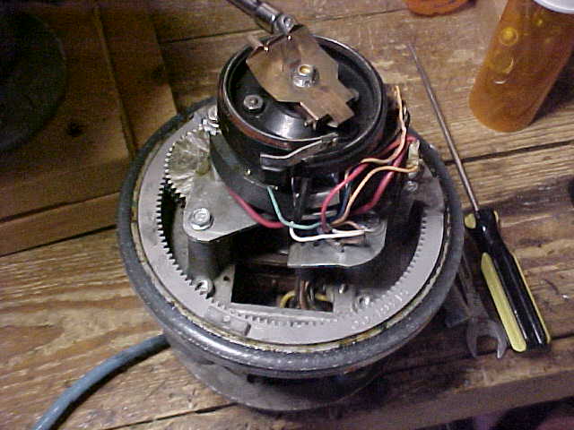
First, I placed the rotator upside down over the 1 1/2" pipe
mounted on the wooden form. This form, shown on the right, was originally used to
hold a portable TV antenna on my travel trailer. The piece with tapered ends is
placed between tandem wheels. It works nicely as a rotator support form too.
It is important to support the rotator, bottom-side up, when you're working on
it. It does not need to be a solid support but you'll want to have your rotor
bottoms up while you work on it.
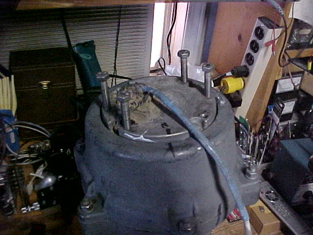
The 4 longer bolts facing up are bolts used to hold the rotator to the rotor shelf
on the tower. The replacement rotor uses different sized bolts so when this one was
brought down, I kept its bolts with this rotor so they wouldn't get lost or used for
something else.
Note that the Ham-M series rotators use 4 bolts to hold the two halves together,
the Tail-Twister has 6 bolts. Don't pay any attention to the messy workbench -- lots
of simultaneous projects going.
Remove the 6 bolts and nuts (plus the 4 others mentioned above) and place all of
them in an empty pill bottle. That's what those amber-colored bottles are and they
help me keep track of removed hardware.
|
|
When I opened the rotator up, the grease was fairly dry
and didn't look like it was doing much lubrication. Not sure how he got in but there was a
dead spider inside the top bell. He was about 1/4" long in his current condition and
I'm sure he had some interesting rides around on the wiper of the direction indicating
potentiometer before assuming his current condition. I haven't found any small
particles of broken metal pieces inside so I'm already encouraged with this.
As mentioned in another article about repairing antenna rotators, it's a
good idea to mark the two case pieces with a magic marker so they can be matched up easily
when reassembling. I also mark the bottom plate of the rotor (the one which rotates
when it is upside down, and the bottom shell of the rotor. The Tail-Twister does not
seem to be as critical along this line as some of the units in the Ham-M series. I
actually did mark my cases before disassembly but ended up painting over the marks.
It might help you to mark them, it shouldn't hurt anything, but you'll need to make some
other provisions if you plan to repaint your Tail-Twister as I did.
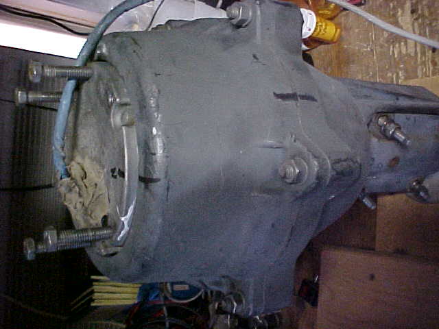
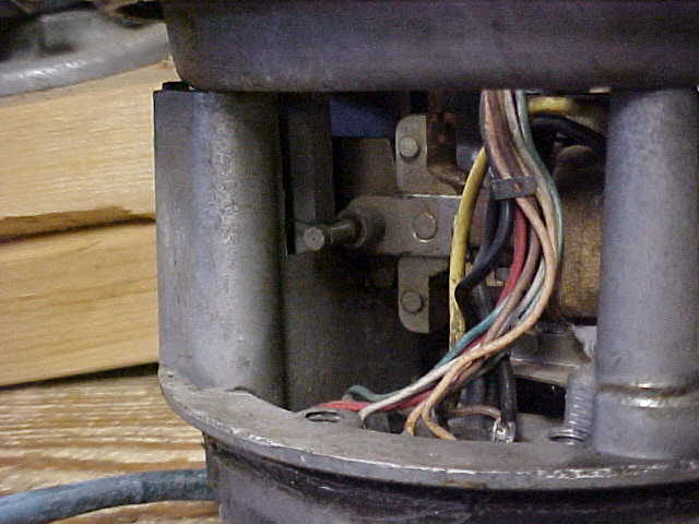
An observant reader will see some atrocious-looking goo covering the screw
terminals on the bottom of the rotor. This is the way I chose to seal or
weatherproof the screw terminals. All of my rotors are the older type which have
screw terminals for the 8 connections instead of the newer socket. I attached the
wires of the rotor cable, then covered the area with black RTV silastic rubber
compound. In recent years I have read about the vinegar-smelling goo causing
problems with some connections over time but since it's been on there for several decades
and I'm not aware of any of my rotor problems being caused by these connections, I'm going
to not worry about it. It's kinda like asking the 98 year old man if he didn't think
he should stop his smoking so he could live longer. |
|
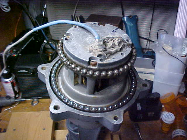 |
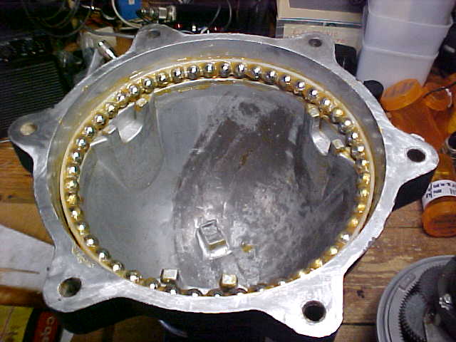
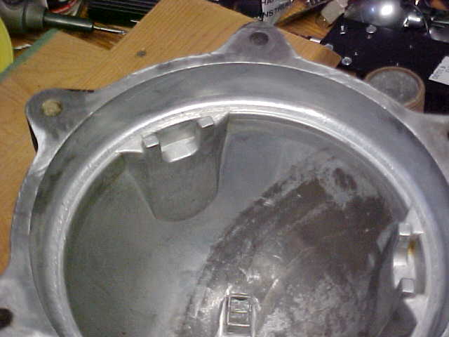
Once the motor assembly was separated from the bearing races, the
bottom bell containing the brake "engagement slots" I looked over things, trying
to find any obvious damage. A recent message on the TowerTalk reflector talked about a
Tail-Twister which was slow running in one direction. His later message described the
problem he had found with a broken gear shaft so I was looking, in particular, for that
being a possible solution to my problem. See message below:
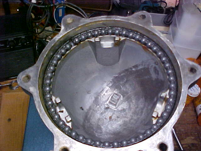
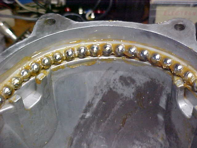
The plastic bearing holders have a flange on one
side. Take careful note of the way this flange is seated, whether up or down.
You'll need to know when you put it back together. On my Tail-Twister, the
small and large bearing races (the first to be removed with the rotor upside down) both
had the flange down. The smaller bearing race holds 40 ball bearings. The
larger bearing race (the middle one in the rotor) holds 49 bearings. |
|
At 04:41 PM 1/28/2008, Mike wrote:
Need some ideas on where to look to find out why the T2X turning in the
CCW direction is slower than in the CW direction.
Recently noticed my T2X takes longer to turn in the CCW direction
than in the CW direction. Wind is not the reason as slow CCW
direction turning occurs even with ~0 wind. The phase capacitor is
mounted at the T2X and the power and position indicator lines are,
respectively, #12 and #14 gauge wire. The capacitors are several years
old and mounted in a water resistant box (small vent hole on the bottom).
The T2X is ~ 250 ft from the in-shack control box.
The T2X is turning a EF240X and a 4 el. SteppIR on a 2" dia., 1/8"
wall, 21 ft chrome-moly mast. The mast and ant. weight are
supported by the T2X. Sixteenth inch shim stock is used to center
the mast in the T2X. Thrust bearings are used to center the mast but not
for supporting the mast and ant. weight. The T2X is mounted 8 ft from
the top of the tower. Several months ago the T2X's mounting bolts and
thrust bearing mounting bolts were checked for snugness.
This CCW rotation slowness was just noticed this last month when the
weather turned cold. The last several years the T2X rotated the
mast/ant. equally the same speed in both directions.
73, Mike, K4GMH
From: Mike <k4gmh@arrl.net>
Subject: Re: [TowerTalk] T2X Slow CCW Rotation Problem
Date sent: Thu, 06 Mar 2008 14:15:03 -0500
Hello,
The problem with the rotor is the rod holding the series of gears
used to turn the internal ring gear and the rotor had sheared off in two
places.
When the rotor housing was first removed, noticed the drive gear was
wobbling. The wobble is the reason for the delayed start in the CCW
direction as it wasn't engaging the ring gear at start up. This same
thing, post shearing off, happened three years ago and the T2X part was
replaced. Probably a good indication that its trying to turn too much
ant.
73, Mike, K4GMH
|
Brake wedge |
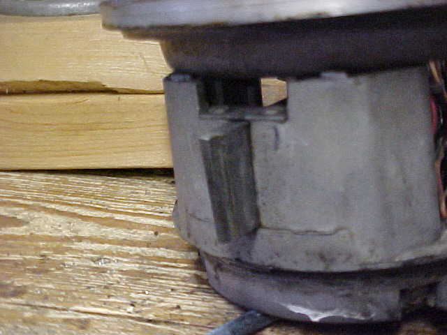 |
| Brake solenoid |
 |
| Brake engaging grooves |
 |
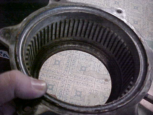
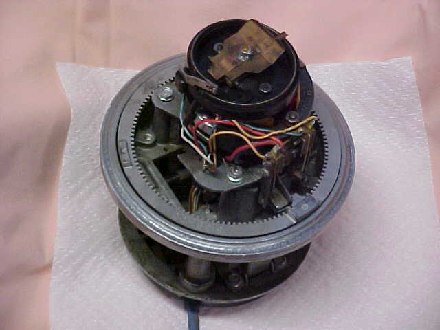
Top bell with upper
bearing race (old race with dried grease) |
 |
All the gears in my Tail-Twister seemed to be secure with no
broken posts. I hooked power back up to the motor and turned it all the way CCW. It moved
the ring gear around normally and tripped the end of rotation switch, just as it should.
Remember this is a stainless steel ring gear and not the cast metal type used in the older
Ham II, III, etc. series. I turned it back CW and it turned beautifully until it got to
what would have been the eastern direction on my tower, and it stopped. The motor
continued to turn, as long as I kept my finger on the switch, but the rotation on the ring
gear had stopped.
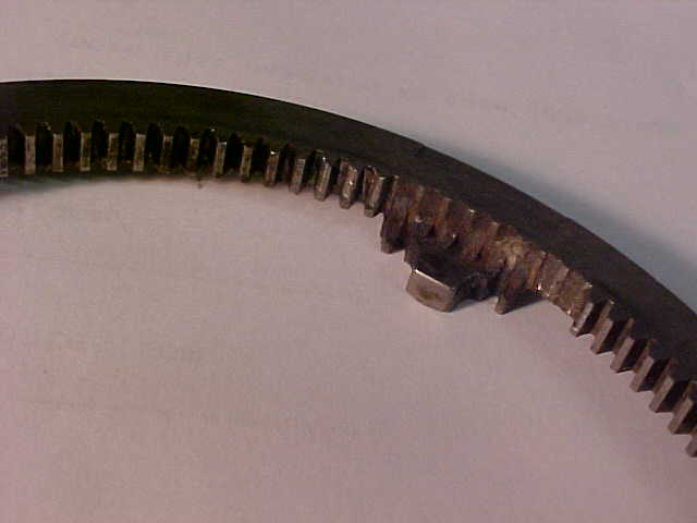 |
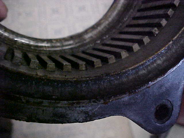
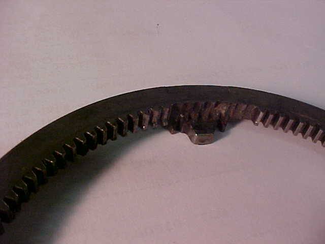
Still, I didn't see what might be causing this, however, as soon as I
dug out my extra bright flashlight, the problem became evident. Eight teeth on the ring
gear were missing but they had not been apparent when I first looked because the missing
teeth were directly under the stob which trips the end of rotation switches. In addition,
there were 3 teeth partially chewed down from 1/4 to 3/4 of the height of a normal tooth.
Once I knew what I was looking for, I could look back down on the ring gear and see
several of the teeth missing which were unshielded by the stob. In no other spot around
the ring gear were any teeth even partially damaged. It would be interesting to
learn what caused those teeth to be broken out of just that one area. Perhaps, some day I
will sit with my feet propped up and the cleaned-up culprit ring gear in hand and
contemplate the possibilities of the damage. |
 |
The cure became simple, replace the stainless-steel ring gear with
another of the same material (but several more good teeth) and continue the clean-up,
lubrication, and repainting of the Tail-Twister. Fortunately, I like to keep a spare
stainless steel ring gear and a spare direction indicating potentiometer. It was an
easy fix for me. This old antique may outlive me now.
|
 |
|
Cleaning the parts became quite a challenge. Ideally, if a
person had a solvent dunk-tank, they could let the pieces (with the exception of the motor
assembly) have a good soaking. If you had such a tank, or know a mechanic who has one, I
would recommend it highly. Unfortunately, I did not have one nor did I know anyone who did
so I had to do it all by hand, like the early pioneers did.
|
The bottom bell, which has the brake-engaging grooves, showed a lot
of places where dust/dirt and grease became mixed together and solidly adheres to the
walls of the metal. It's in the grooves, the machined bearing runs, and any little nook or
cranny it can find. I wore out numerous wooden toothpicks scraping this gunk off the
rotor's insides. It's not an easy task but I believe it is well worth the time I spent
doing it. If I had owned one of those brass-bristle toothbrushes (hhmmm, I guess those
aren't really toothbrushes but they're about the same size) I would have used that on the
grooves. I didn't, so I didn't. When I reassemble my rotator, I want the
metal inside it to look as shiny as a baby's behind..... no wait, that phrase is soft as a
baby's behind, isn't it? Oh well, I want the metal to look like the day it was
manufactured. This rotator resides in a place I personally can't get to and must depend on
my friends to make any changes. I hope my friends will always be around to help
but............... I'd better go do something extra nice for my friends.
An air compressor with a good on/off blower nozzle is mighty handy here too. Once some of
the pieces of gunk are loosened, it helps to use air to blow them free. That air blast can
find hidden pieces as well or better than your bifocals or trifocals. |
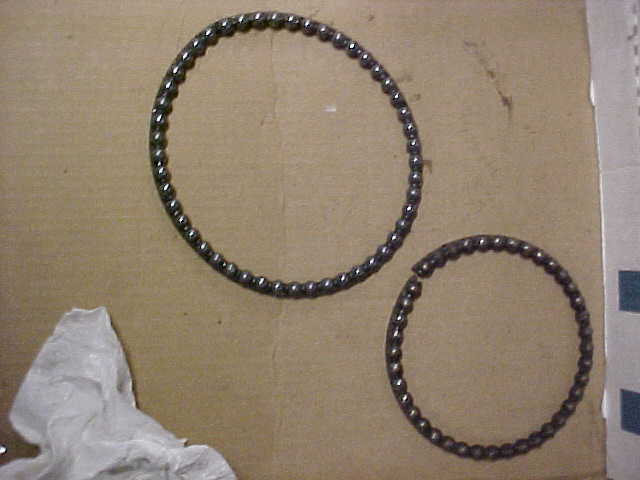
Here's a couple of the old ball bearing races |
Once I had begun to clean up my ball bearing races and get the old
grease off them, I discovered that many of the bearings had rust spots. They weren't
particularly severe rust spots but any rust can be detrimental to a smooth movement of the
bearings. Since I had seen rust on the bearings when I previously rebuilt my Tail-Twister,
I had already bought some replacement bearings and replacement bearing holders at an
earlier hamfest when MFJ had a booth. The ball bearings are sold as a package of
supposedly 48 bearings and two plastic bearing holders for $14.95. The package is labeled
"Ball Bearing Kit for HAM-IV P/N"5131010 hy-gain" I thought, at first, that
the actual bearing holders from my Tail-Twister seemed to be a little better built than
the replacement holders in the package. They seem to hold the bearings better when you
move the assembly around for cleaning. Actually, I discovered that the reason the old ball
bearings held fast to the holders was, the grease had dried out and was holding them in
like a cheap glue. Originally, when I rebuilt my Tail-Twister I had bought replacement
ball bearings from a bearing place in Tulsa and I'm sure they were much less expensive
than the packages from MFJ but I wasn't around the bearing place, I didn't plan to be
around the bearing place, gasoline is getting more expensive and the MFJ booth was right
in front of me. Suffice it to say that there are several ways you can get your replacement
ball bearings. |
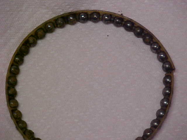
One of the old races with rusty ball bearings and dry grease
|
Most of the rusted bearings were in the smaller race which fits
in the bottom area of the rotator, below the motor assembly. The bearing race holds only
40 bearings whereas the larger two races hold 49 bearings each. I believe that these were
the most rusted because the bottom of the rotator provides the poorest seal against the
weather. When mounted normally, the rotor body does shield this area but there is still a
space which must be there to allow the rotator to rotate. Dust, moisture, and evidently my
spider were able to enter the unit at this point.
By the way, MFJ didn't seem to have a specific package listed for the Tail-Twister, only
the HAM-IV (Ham-M series). The third bearing race, the one mentioned above from the lower
run and with the rusted bearings, is actually smaller and takes fewer ball bearings. This
means I'll have some left-over bearings when my project is complete. If you are
buying the replacements from MFJ for a Tail-Twister project and they only had the same
package they offered to me, you will obviously need two packages.
The more I checked the metal machined tracks attached to the motor assembly, the more I
found much evidence of the goopy material made up of dust/dirt and dried grease. It clings
to every piece and needs to be completely removed down the to original bare metal. Not a
particularly easy job but a necessary one. It seems to hide too. Clean, inspect, and clean
some more. Put the piece aside for a while and when you come back to it, you'll probably
find more goopy stuff which also needs to be removed. I even used a quantity of Q-tips
with solvent to clean those hard-to-get-to places. I'm quite sure, when I rebuilt my
Tail-Twister back 6 years ago, I did not check it as carefully as I did this time. I
didn't remove any but the most obvious goopy stuff back then. Of course, that may explain
why it lasted 26 years until its first rebuilding but only 6 years until the second. I
recommend you spend lots and lots of time cleaning it up while you have it opened up. This
may also explain why you thought it was too expensive to send your rotor to a commercial
rebuilding facility that advertises in QST. If it's done correctly, you'll spend
some time in the effort.
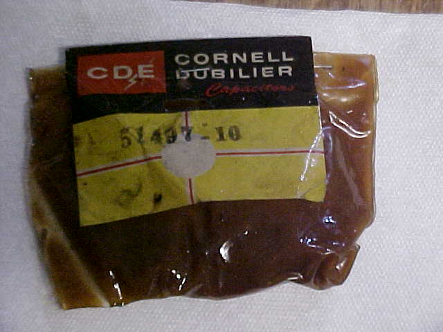
| The next task at hand was to lubricate the internal workings of the
rotator. This was discussed in the other article on the website about rebuilding
rotators. I used a different grease for that rotator and it worked well but after
doing that rotor, I discovered an antique plastic packet of grease sold by CDE for their
rotors. This came from the time I owned a ham store (Derrick
Electronics in Broken Arrow, OK) which would have been during the
1970s. I suspect this packet of grease was purchased around 1978 or so and was still
just as greasy and as messy as the day it was bought. The picture shows this package
and, although I have used from it at least twice, it still has plenty. I don't know
if it is still available or not. If you're interested in tracking down some of this
grease, I would suggest a call to MFJ to see if that was one of the items passed down from
CDE to Hy-Gain to MFJ. |
|
|
Once the parts were all cleaned up, it was time for
re-assembly. With the pieces apart, it was easy to repaint the rotor shell.
The previous paint had changed to a dull gray color so I used a can of flat black spray
paint. If a sand-blasting facility had been available, I would probably have had
the outer shells sand-blasted but that was not available. Since it's mostly the
birds and the wasps that get to see it, I didn't want to spend too much time in making it
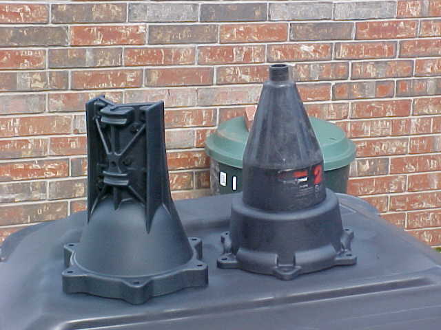
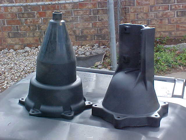
too pretty. It was important to keep the paint out of the large hole in the bottom
of the lower shell so I was able to find a nice plastic funnel (purchased several years
ago at Wal-Mart) to completely fill the hole. It served perfectly and kept any paint
spray from entering the inside of the rotor. |
|
 |
Here are the two outer shells, complete with their new flat black
paint job. Note that I did take out, i.e. did not paint, the stainless steel U-bolts
and the other clam-shell piece used to hold the mast tightly against the taller V-shaped
piece on the top of the rotator. |
|
|
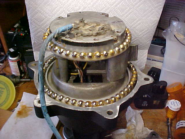
It's hard to adequately describe how to grease
the new set of ball bearings and plastic races. There's just simply no way to do it
delicately -- or cleanly. First, as mentioned in the other article, you should
ALWAYS work over some type of container with small sides to capture the ball bearings when
they accidentally fall. Notice that I did not say "if they accidentally
fall," I said "WHEN they accidentally fall" and they will
fall. Load the bearing races, one at a time, then squeeze out a small amount of
grease onto your finger and work that grease into the race on each side of the
bearing. It's a process akin to repacking a vehicle's wheel bearing. Work the
grease into the race on both sides of the ball, squeeze out more and continue around the
entire race. Resist the urge to do this too quickly, take your time and do it right.
When you are finished, there will be grease evident on both sides of each ball
bearing, all the way around, but there will not be any extra blobs of grease which can
fall off and get somewhere where it shouldn't be. How much grease is enough?
Well..... just enough. If you finish greasing up one bearing race and your fingers,
and maybe your hands, are a mess and you're looking around for a paper towel, it probably
is greased well enough.
The next step is to place the greased bearing race back on the
rotor. At first, you should have the top bell turned upside down on the workplace.
The race is c-a-r-e-f-u-l-l-y lifted from the box or lid where you've been working
and place it into the rotor on the metal track machined to receive it. It is
possible, since the grease is a makeshift adhesive, to get the race into place and not
drop any bearings. I did not say it was guaranteed but it is possible. Once
it's in place it's time to find another paper tower --- that other one has already
outlived its useful life. The rotator now looks like the pictures on the left and
right.
|
|
Now you're ready to assemble the motor assembly to the rotor
upper bell. This operation can be quick and easy and highly successful or can be one
of the most frustrating activities you've encountered since first trying to learn the
morse code. Several pieces must be identified:
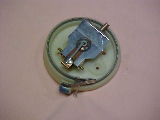
| The direction tracking piece - the piece attached to the
potentiometer's center (wiper) arm which has a rather W-shaped piece. This piece
should ......no...... MUST fit correctly into the raised boss at the top inside of the
upper rotor bell housing. |
|
| The is the boss in the bottom of the bell and, although
the picture may not show it well, you must identify the two raised parts which will fit
inside the valleys of the W-shaped piece above.
Caution: If the top piece on the
potentiometer is not correctly placed on the two raised pieces on the boss, the rotor will
not (cannot) indicate the direction where your beam is aimed. If you get it off to
one side or the other of the boss, the potentiometer's wiper may be pushed around (and
actually indicate movement) for only one time. When the rotor comes back the other
direction, it cannot be pulled back for the indication meter will remain at the extreme
where it was pushed. |
|
|
Having said that, it's time to place the motor assembly in
place. When I do this activity I place the potentiometer wiper in the center of its
rotation. I also make sure the "stop stob" on the ring gear is sitting
180 degrees away from the end stop switches. This activity is done, regardless of
whether you use an indicator with a North-center scale or a South-center scale.
NOTE: This picture shows the stop stob at
the extreme rotation position where it has tripped the end stop switch. When you
insert the motor assembly, the ring gear should be manually moved so the stop stob is on
the other side, 180 degrees from where shown. The wiper on the potentiometer is
centered correctly in the picture.
If you only plan to take your time once during this whole
process, now is the time. The W-shaped piece on the potentiometer MUST seat itself
properly on the boss. Personally, when I do this and have the motor assembly sitting
in what seems to be the correct position, I hook up the indicator box and test it
out. You still don't have the bottom housing on the rotor but the weight of the
motor assembly will hold it down properly and you do have a good set of greased bearings
for it to ride upon. When you hook up the indicator, if you've done all I've
mentioned a couple of paragraphs ago, the meter should indicate at the center of the
scale. You should be able to turn the rotator CCW and when it gets to the end of
that 180 degree rotation, the rotor motor should automatically stop. The meter
should be showing all the way at minimum. Now you can turn the rotor all the
way clockwise. When it gets to the full 360 degree rotation the other way, the motor
and all rotation should again stop.
|
Did
the meter follow the rotation back and now indicate full scale? If it did,
congratulate yourself --- you hit the right position with the top of the motor
assembly. You've just accomplished the most difficult part of rebuilding the
rotator.
Oh, but you say it didn't
track to full scale? Then it's time to pull the assembly back out, set the wiper to
the center of the pot, move the ring gear's stop stob to 180 degrees away from the end
stop switches and try again. A successful repair/rebuild/reconditioning operation
must succeed at this step or you must not continue on to completion. |
Assuming that all is OK, i.e., the first set of greased ball
bearings is seated correctly, the motor assembly is correctly inserted in the top bell
housing, the rotor is able to rotate a full 360 degrees and the motor stops completely at
the end of each rotation, and (most importantly, at this point) the meter indicator moves
from zero scale at one extreme rotation to full scale at the other extreme rotation and
keeps following the rotation, regardless of where the rotor position is moved.
You're now on the home stretch, but wait!!!!!! Don't get in too much of a hurry because
that's how ball bearings get accidentally knocked out of the race and roll under the work
cabinet or down the heater and air conditioner vent in the floor. Of course, since
you had some left over ball bearings, the one that dropped is still findable but if you
only had just enough, that puppy that dropped would now be in China.
Take the second larger plastic bearing race and load it up with
its 49 ball bearings while you still have the whole thing in a box with small sides or a
larger box top. Completely grease up the race as described above. Use enough
grease because it's going to be up there on your tower, unattended, for the next 5, 10,
maybe 20 years without needing any intervention from you (we can dream, can't we?).
Immediately, while your hands and fingers are still greasy, place this bearing race in
place in the rotor housing, paying particular attention to which way the race's flange is
pointing (you did write down that information when you started, didn't you?)
When that race is in place, you'll want to finish up the bottom
bearing race. Actually it's at the top of what you're working on since you should
still have the rotor upside down on the workbench. This plastic bearing race will be
too long as it comes from MFJ so you'll need to trim it down. The piece, as it comes
from the package, will hold a total of 49 bearings but this last race is smaller and
should only have 40 balls. It can be trimmed easily with a pair of side-cutters but
I must caution you with the old carpenter's axiom: "Measure twice, cut
once" I suggest counting from one end to the 40th hole and count backward
from the other end to make sure there were 9 other spaces. Once the race is trimmed,
the last bearings should be inserted and greased up as above.
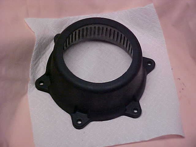
| The completed greased bearing race can be now placed in its proper
place atop the motor assembly. The same caution mentioned above is important here
too, make sure the flange is place correctly for the race.
This picture shows all three bearing races in place (the lowest
one is covered by the motor assembly already so it can't be seen) and the bottom shell is
ready to be placed back on the rotator. Note the brake wedge sticking out on the
right side between the two sets of races. |
|
Now it's time to clean up those hands --- they're probably too
messy now for just paper towels and may require a trip outside to rub them in the grass or
on the family sheepdog. Perhaps a trip to whatever room has the Lava soap is your
safest bet.
Now the bottom shell of the rotator, perhaps now well cleaned up
and freshly painted, is ready to be mounted back on the complete assembly. There
doesn't seem to be any particular way to mount this, besides making sure the 6 bolt holes
line up, but you will probably need to manually push the brake wedge back in so the shell
fits down easily. I'd also be careful not to rattle the whole thing around too much
to make sure the last two bearing races stay in place. Once the bottom shell fits
against the top bell housing, you can place the bolt, lock washer, and nut in each hole
and tighten things up. How tight? Well, I wouldn't try to tighten them right
after I had a 20 oz steak but I try to remember that they're going to be up there where
I'm not........... and have no intention of going.......... EVER, so I get them good and
tight. The ears on a Tail-Twister case don't seem to be a such an angle that
overtightening might break one off but I try to be somewhat gentle....... in a rugged sort
of way.
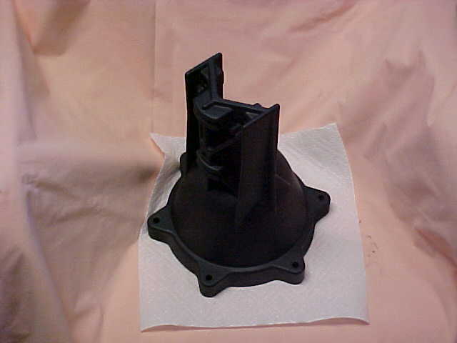
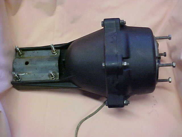
| Here's my Tail-Twister, all rebuilt, relubricated, repainted, and
ready to go up on my tower to provide my SteppIR with many more years of service.
Perhaps hundreds of DXpeditions, thousands of contacts and many, many hours of total
satisfaction await me in the greatest hobby around, Amateur Radio. Jim
- K5LAD
Added Note: I've had several people interested in using
my TailTwister repair article for their club newsletter or to save a copy for their "I
Hope I Never Have to Use This But I Sure Want to Have It If I Need It"
file. It seems to be difficult to pull it from the website pages so I've made it
available as a download, pictures and all. Click on Repairing a TailTwister
Rotator and you should be able to download a .pdf copy.
Permission is freely granted to use it for your club's
newsletter but I would appreciate it if you'd give me credit and let me know you've used
it. Either send me a copy or, if your newsletter is published on a website, send the
URL where it's located. Thanks and 73,
Jim - K5LAD
| 
|
Page visited 4129 times
Created April 12, 2008 The page was updated on 10/01/09 04:56 PM
Click
to return to Rotor Repair Menu  Click
to return to Home Page
Click
to return to Home Page 